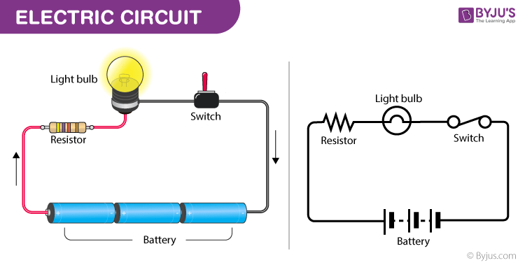
We know there are various components needed to build an electrical circuit. To understand the electrical circuit completely and to know the flow of current one must understand the electrical symbols of circuit components. In this session, let us discuss in brief about electrical symbols of circuit components.
| Table of Contents: |
What is an Electric Circuit?
A system of conducting elements that are designed to conduct electric current for a particular purpose is known as an electric circuit. An electric circuit consists of a source of electrical energy; elements that either transform, dissipate, or store this energy; connecting wires. To prevent power overload, circuits often include fuse or circuit breaker.

A Short History of Circuits and Systems
The first electric circuit was invented by Alessandro Volta in 1800. Volta discovered that he could produce a steady flow of electricity using bowls of salt solution connected by metal strips. Later, he used alternating discs of copper, zinc, and cardboard that had been soaked in a salt solution to create his voltaic pile (an early battery). He successfully made the electric current to flow through the circuit by attaching a wire running from top to bottom. The first practical use of electric current was employed in electrolysis, which further led to the development of new chemical elements.
Components of an Electric Circuit

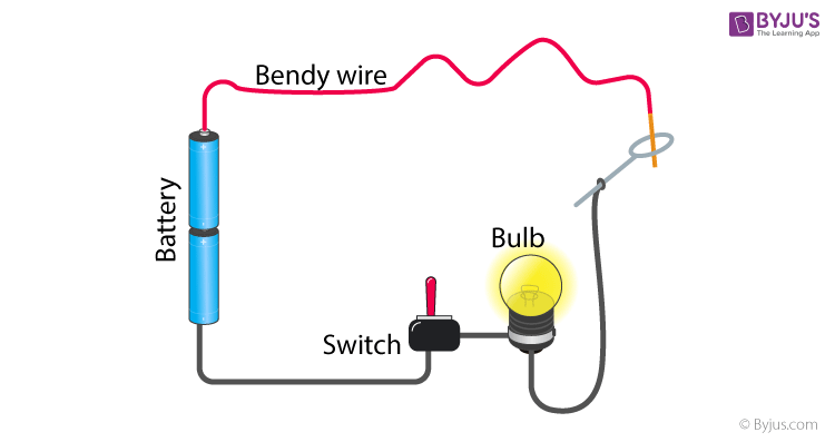
Electric circuits are amazing. Have you ever seen the game of Steady Hands? It is a circuit with a twisty wire between two points. The point of the game is to move a metallic object from one end of the electric wire to the other. If you touch the wire while moving this metallic object, the circuit buzzes and you are out. It’s a really fun game that can be made with stuff you can find at home. Let’s analyze an electric circuit and dive deeper into its components.
See the video below, to understand the flow of current.

List of Electrical Components With Symbols
Electrical symbols are a graphical representation of electrical and electronic components. These symbols help us recognise a particular electronic device in a circuit. Electrical symbols are defined with national and international standards. These symbols only represent the components of electrical and electronic circuits and do not define their function or process.
Let us have a look at how various components in a circuit are denoted:
|
Wire Symbols |
||
|
Name of the Component |
Component Description |
Symbol |
|
Electrical Wire |
A wire is a single, usually cylindrical, flexible strand or rod of metal through which electric current flows. It is usually made of good conducting metals such as copper. |
|
|
Connected Wire |
Connecting wires provide a medium to an electrical current so that they can travel from one point on a circuit to another. |
|
|
Not Connected Wire |
In diagrams, we come across situations where we have wires crossing through other wires even though they are not connected to each other. Hence, it is preferred to have a hump as shown to depict the crossing of wire over another wire. |
|
|
Ground Symbols |
||
|
Earth Ground |
The reference point in an electrical circuit from which voltages are measured, a common return path for electric current, or a direct physical connection to the earth. |
|
|
Chassis Ground |
Chassis ground is the metal housing that some electrical device is encased in. The chassis may be connected to the green ground wire of your power lines. |
|
|
Digital/Common Ground |
The reference voltage of digital logic ICs. This means that no analog signals are coupled into this reference plane. |
|
|
Light Bulb Symbol |
||
|
Lamp/ Lightbulb |
It is a load that uses electric current to emanate light |
|
|
Resistor Symbols |
||
|
Resistor (IEE)/(IEC) |
A resistor is a device that resists the flow of current through a circuit |
|
|
Variable Resistor/ Rheostat (IEE)/(IEC) |
|
|
|
Potentiometer (IEE)/(IEC) |
A potentiometer is a three-terminal resistor with a sliding or rotating contact that forms an adjustable voltage divider. |
|
|
Photoresistor/ Light-dependent resistor (LDR) |
Photresisor decreases resistance with respect to receiving luminosity |
|
|
Thermistor |
A thermistor is a type of resistor whose resistance is dependent on temperature |
|
|
Capacitor Symbols |
||
|
Capacitor |
A capacitor is a device that stores electrical energy in an electric field. |
|
|
Variable Capacitor |
A variable capacitor is a capacitor whose capacitance may be intentionally and repeatedly changed mechanically or electronically. |
|
|
Polarized Capacitor |
A capacitor whose anode is made of a metal that forms an insulating oxide layer through anodization. |
|
|
Power Supply |
||
|
Voltage Source/ Current Source |
A voltage source is an electrical component that can maintain a fixed voltage irrespective of the load resistance and output current |
|
|
Battery Cell/ Battery |
A battery is a device that consists of two or more electrochemical cells with external connections. |
|
|
AC Voltage Source |
It is a source hose positive and negative terminals change periodically |
|
|
Controlled Voltage Source/ Controlled Current source |
|
|
|
Meter Symbols |
||
|
Voltmeter |
An instrument for measuring electrical potential. |
|
|
Ammeter |
An instrument for measuring electric current. |
|
|
Diode Symbols |
||
|
Diode |
A semiconductor device with two terminals that allows current to flow only in one direction. |
|
|
Zener Diode |
A diode that allows the flow of reverse current when it reaches a certain Zener voltage. |
|
|
Schottky Diode |
A diode formed by the junction of a semiconductor with a metal. |
|
|
Varicap Diode |
A type of diode designed to exploit the voltage-dependent capacitance of a reverse-biased p–n junction |
|
|
Photodiode |
A type of a semiconductor device that converts light into an electrical current. |
|
|
Transistor Symbols |
||
|
NPN Bipolar Transistor |
The transistor in which one p-type material is placed between two n-type materials |
|
|
PNP Bipolar Transistor |
The transistor in which one n-type material is placed between two p-type materials |
|
|
Logic Gates Symbol |
||
|
OR/NOR Gate |
|
|
|
AND/NAND Gate |
|
|
|
XOR/ NOT Gate |
|
|
Watch the video below to learn more about electricity and resistance.

Hope you have learned in detail electrical symbols. Stay tuned to BYJU’S and FALL in Love with Learning!. Watch more interactive videos and make learning a lifetime experience, download BYJU’S – The Learning App.
Frequently Asked Questions – FAQs
What is a motor?
Motor is a device that has the capacity to convert electrical energy into mechanical energy.
What is a photodiode?
A type of a semiconductor device that converts light into an electrical current.
What are electrical symbols?
Electrical symbols are a graphical representation of electrical and electronic components.
Which conducting material is used in electrical wires?
What is an electrical fuse?
A fuse is a protective device that protects circuits against the flow of excess electrical current.


great