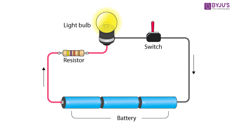
A resistor is a passive two-terminal electrical component that implements electrical resistance as a circuit element. Resistors reduce the current flow and lower voltage levels within circuits. Most circuits often have more than one resistor to limit the flow of charges in a circuit. The two simplest combinations of resistors are – series and parallel. In this article, we will be discussing resistors in series and parallel combinations.
| Table of Contents: |
Circuit Components

A circuit is composed of conductors (wire), power source, load, resistor, and switch. A circuit starts and ends at the same point. Usually, copper wire without insulation is used as a conductor. A switch is used to make or break a circuit. Resistors control the flow of the electric current in a circuit. A resistor is a passive element which means that it only consumes power but does not generate power. A load in a circuit consumes electrical energy and converts it into other forms of energy like light, heat, etc. A load can be a light bulb, fan, etc. Now let us know about resistors in series and parallel combinations.
Read more:Types of Switches
Need of a Combination Circuit
In an electric circuit, the different components are connected either in series or in parallel to produce different resistive networks. Sometimes, in the same circuit, resistors can be connected in both parallel and series, across different loops to produce a more complex resistive network. These circuits are known as mixed resistor circuits. In the end, however, the total resistance should be known. It is important to know how to do this because resistors never exist in isolation. They are always part of a larger circuit that will have many resistors connected in different combinations. So how do we calculate this total resistance for resistors in series and parallel circuits? In the next section, let us have a look at how to find the total resistance for resistors in series and parallel combinations.
See the video below and know about power dissipated across the resistor.

Resistors in Series
A circuit is said to be connected in series when the same amount of current flows through the resistors. In such circuits, the voltage across each resistor is different. In a series connection, if any resistor is broken or a fault occurs, then the entire circuit is turned off. The construction of a series circuit is simpler compared to a parallel circuit.

Resistors in series combination
For the above circuit, the total resistance is given as:
For example, consider the following sample problem.
A resistor having an electrical resistance value of 100 ohms, is connected to another resistor with a resistance value of 200 ohms. The two resistances are connected in series. What is the total resistance across the system?
Here, R1 = 100 Ω and R2= 200 Ω
Rtotal = 100 + 200 = 300 Ω

Resistors in Parallel
A circuit is said to be connected in parallel when the voltage is the same across the resistors. In such circuits, the current is branched out and recombines when branches meet at a common point. A resistor or any other component can be connected or disconnected easily without affecting other elements in a parallel circuit.

Resistors in parallel combination
The figure above shows ‘n’ number of resistors connected in parallel. The following relation gives the total resistance here
For the problem given above, what if the resistors were connected in parallel instead of in series? What is the total resistance in that case?
=
=
Therefore,
Summary
- A circuit is composed of conductors (wire), power source, load, resistor and switch.
- Resistors control the flow of the electric current in a circuit.
- A circuit is said to be connected in series when the same amount of current flows through the resistors.
- The following relation gives the total resistance of a series circuit:
Rtotal = R1 + R2 + ….. + Rn
- A circuit is said to be connected in parallel when the voltage is the same across the resistors.
- The following relation gives the total resistance of a parallel circuit.
\(\begin{array}{l}\frac{1}{R_{total}}\end{array} \)=\(\begin{array}{l}\frac{1}{R_1}~ +~ \frac{1}{R_2} ~+~ ….~ +~ \frac{1}{R_n}\end{array} \)
- Sometimes, in the same circuit, resistors can be connected in both parallel and series, across different loops to produce a more complex resistive network. These circuits are known as mixed resistor circuits.
Hope you have understood how to find the total resistance for resistors in series and parallel combinations.

Frequently Asked Questions – FAQs
What is a resistor?
State true or false: copper wire without insulation is used as a conductor.
True.
What is the formula to calculate the total resistance in series combination?
Rtotal = R1 + R2 + ….. + Rn
What is the formula to calculate the total resistance in parallel combination?
What is the function of a resistor?
The resistor is a passive device used to control the flow of the electric current in a circuit.


Comments