What is V-I Characteristics?
V-I characteristics stand for voltage-current characteristics of an electrical component or device. The V-I graph yields valuable information about the resistance and breaks down an electronic component. It also provides the operating region of a component. By studying these characteristics we can understand where and how to use a component in an electric circuit.
The voltage-ampere characteristics of an electronic component are its behavior for various values of an applied voltage. Put simply; it is the graph between Voltage and Current obtained when current is measured through an electronic component as a voltage is applied across it.
In V-I characteristics, the Voltage, V is on the x-axis, and the current, I is on the y-axis because it is easier to control the applied voltage rather than current. This makes the voltage the independent variable and is hence traditionally placed on the x-axis.
Types of V-I Characteristics
Linear VI Characteristics
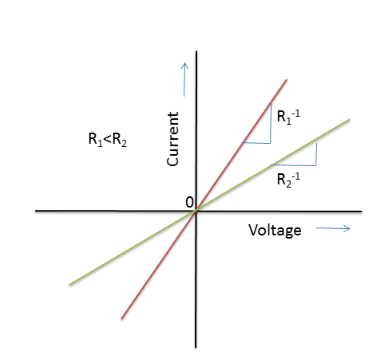
A linear VI curve has a constant slope and hence a constant resistance. Carbon resistors and metals obey Ohm’s law and have constant resistance. This means that the V-I curve is a straight line passing through the origin. An electronic component may exhibit linear characteristics only in a particular region. For example, a diode has a mostly linear behavior in its operating region.
Non-linear VI Characteristics
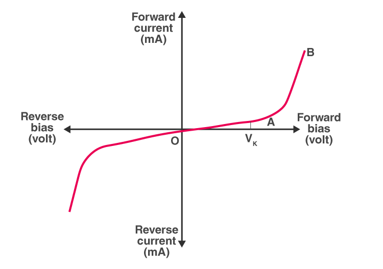
A circuit component has a non-linear characteristic if the resistance is not constant throughout and is some function of voltage or current. The diode, for example, has varying resistance for different values of voltage. However, it has a linear characteristic for a narrow operating region. Note that in the graph below we can also see the maximum forward and reverse voltage in which the diode can be operated without causing breakdown and burning up of the diode.

V-I Characteristics of SCR
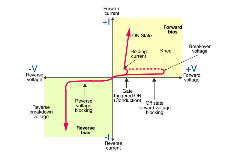
SCR stands for the Silicon Controlled Rectifier which is a three-terminal semiconductor switching device that is used as a controlled switch for rectification, regulation, and inversion of power flow.
The V-I characteristic curve of SCR is between the anode-cathode voltage, V, and anode current, I at constant gate current. Below is the graph explaining the V-I characteristic of SCR:
V-I Characteristics of MOSFET
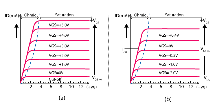
MOSFET stands for Metal Oxide Semiconductor Field Effect Transistor which is one of the types of FET transistors. These transistors have three terminals and they are a drain (D), source (S), and gate (G), and the fourth terminal is known as substrate. These transistors are classified into two:
- Depletion type transistor
- Enhancement type transistor
The V-I characteristic of MOSFET for both the classifications are given below:
V-I Characteristics of LED
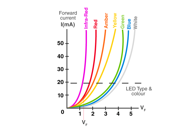
LED stands for light-emitting diode which is used in all types of semiconductor diodes with electrical characteristics similar to a PN junction diode.
The V-I characteristic of LED is given below:
V-I Characteristics of PN Junction Diode
When an N-type material (has more free electrons) is fused with the P-type material (has more number of holes) to create a semiconductor diode, it is known as PN junction diode. There are three biasing conditions and they are:
- Zero bias
- Forward bias
- Reverse bias
The V-I characteristic of PN junction diode is given below:
Related Article:
V-I Characteristics of Zener Diode
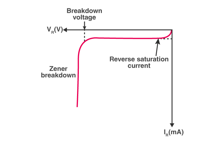
A Zener diode is a device which works in the Zener breakdown region. When these diodes are forward biased, they act like p-n junction diode. These diodes have a very thin depletion region as they are heavily doped allowing more electric current than regular p-n junction diodes.
The V-I characteristic of Zener diode is given below:


Comments